3D Printing Tolerances: A Practical Guide to Parts That Fit
Standard FDM 3D printing tolerances are roughly ±0.2mm, and a well-calibrated machine can reach ±0.1mm on small parts. That means two parts designed to touch perfectly will not fit — you have to design the clearance in. This guide gives you the exact gap values we use across our print farm for press fits, sliding fits, loose fits, threads, and snap fits, plus the four physical factors that push prints out of spec and how to design around them.
3D Printing Tolerances in mm: Clearance for Each Fit
| You want | Design this gap | Notes |
|---|---|---|
| Press fit (bearing, dowel pin, magnet) | 0.05–0.1 mm per side | 0.1–0.2 mm on the diameter; chamfer the lead-in 0.5 mm |
| Snug or tight fit (stays put, comes apart by hand) | 0.1–0.2 mm per side | Between press and sliding: print a test coupon to settle it |
| Sliding fit (lid, drawer, telescoping tube) | 0.2–0.3 mm per side | Add 0.05 mm when the sliding length is over 50 mm |
| Dovetail or slide rail | 0.2–0.3 mm per face | A sliding fit on each angled face; print both halves in the same orientation |
| Loose fit (hinge, hook, chain link) | 0.4–0.5 mm per side | Falls together freely |
| Hole for a pin or bolt | Model the hole 0.2 mm larger | Holes print 0.1–0.3 mm small; keep the pin at nominal |
| Printed thread | 0.2–0.4 mm radial offset | M8 and larger; below M8 use a heat-set insert |
| Snap fit | 0.3 mm plus a flexing cantilever | Cantilever 4–6 mm wide, 1.5–2 mm thick, printed flat |
Those numbers assume a 0.4 mm nozzle, 0.2 mm layers and PLA or PETG on a calibrated machine, which is how our farm prints by default. ABS and ASA shrink about 1%, so on a large part add clearance in proportion to its size. The rest of this guide explains where each number comes from.
What Tolerance Can FDM 3D Printing Hold?
Tolerance is the allowed deviation between the dimension in your CAD file and the dimension of the physical part. A 20.0mm peg printed at ±0.2mm tolerance can come out anywhere from 19.8mm to 20.2mm. FDM lands at ±0.2mm because the printer draws every surface with a bead of molten plastic roughly 0.4mm wide — the machine positions the nozzle precisely, but the bead swells, shrinks as it cools, and gets quantized into 0.2mm layer steps in the vertical axis. /docs/farm/quality covers the accuracy FDM actually gives you and how a reprint is handled.
Why Holes Print Small and Pegs Print Big
The extruded bead bulges slightly outward from its programmed path. On an outer perimeter that bulge adds material to the outside of the part; on an inner perimeter it adds material toward the center of the hole. The consistent result: outer dimensions run 0.05–0.15mm large, and holes run 0.1–0.3mm undersize. Vertical holes are the worst case because every layer's bead sags a little into the opening.
3D Printing Clearance: How Much Does Each Fit Need?
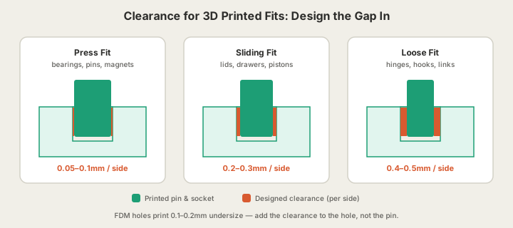
| Fit type | Clearance per side | Feel | Typical use |
|---|---|---|---|
| Press fit | 0.05–0.1mm | Needs firm push, stays put | Bearings, dowel pins, magnets |
| Snug or tight fit | 0.1–0.2mm | Stays put, comes apart by hand | Caps, plugs, covers that stay seated |
| Sliding fit | 0.2–0.3mm | Moves smoothly, no wobble | Lids, drawers, telescoping parts |
| Loose fit | 0.4–0.5mm | Falls together freely | Hinges, hooks, chain links |
| Printed threads | 0.2–0.4mm offset | Threads by hand after 1 turn | M8 and larger fasteners |
| Snap fit | 0.3mm + flexure | Clicks in, releasable | Enclosure clips, battery doors |
Press Fit 3D Printing Tolerance
At 0.05–0.1mm per side the parts interfere just enough that plastic deforms elastically and grips. Chamfer the leading edge 0.5mm so the parts self-align, and press straight — a cocked press fit gouges the bore. For metal inserts like bearings, aim for the tight end of the range; PLA relaxes less than PETG over time.
Snug and Tight Fits
A snug or tight fit sits between a press fit and a sliding fit: 0.1–0.2mm per side, enough that the parts stay put on their own but still come apart by hand. It suits a cap on a tube, a plug in a socket, or a cover that has to stay seated. It is also the fit most sensitive to the individual machine and material: the whole range is narrower than the ±0.2mm FDM holds, so the same clearance can come out snug on one printer and loose on another. Settle it with a test coupon before printing the real part.
Sliding Fits
0.2–0.3mm per side gives smooth motion without slop for parts that mate along one axis. If the sliding surfaces are long (over 50mm), add 0.05mm — small per-layer errors accumulate over travel distance and long parts bind first.
Threads and Snap Fits
Printed threads work reliably at M8 and above with a 0.2–0.4mm radial offset between the male and female profiles; below M8, the 0.4mm nozzle can't resolve the thread form, so use heat-set brass inserts instead. Snap fits need 0.3mm of clearance plus a cantilever that can flex: 4–6mm wide, 1.5–2mm thick, with the hook depth around 1.5mm. Print the cantilever flat on the bed so layer lines run along the beam, not across it.
Why Do 3D Printed Parts Come Out the Wrong Size?
Material Shrinkage
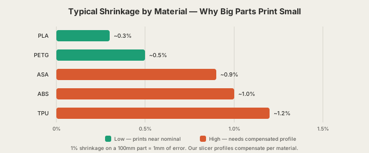
Plastic contracts as it cools from extrusion temperature. PLA shrinks about 0.3%, PETG about 0.5%, and ABS close to 1% — which is why ABS parts measure noticeably small if the slicer profile doesn't compensate. The error is proportional to size: negligible on a 10mm boss, a full millimeter on a 100mm enclosure.
First-Layer Squish
The first layer is pressed into the bed for adhesion, which splays it outward — the classic elephant's foot. It widens the bottom 0.5mm of the part by 0.1–0.3mm and will jam any fit located at the base. Add a 0.5mm chamfer around the bottom edge of every mating feature and the problem disappears.
Cooling and Warping
Uneven cooling makes corners lift and flat faces bow, turning a straight slot into a curved one. Enclosed printers and materials with low shrinkage minimize it; so does designing with rounded corners instead of sharp ones, which concentrate stress.
Print Orientation
XY accuracy (the plane of the bed) is better than Z accuracy, because Z is quantized to the layer height. A hole printed vertically comes out rounder and more accurate than the same hole printed horizontally, which sags into a slight oval. Orient critical bores around the Z axis whenever the part allows it.
How Do You Design 3D Printed Parts That Fit Together?
- Chamfer every insertion edge 0.5mm — parts self-align and elephant's foot stops mattering
- Put all clearance on one part (usually the hole) and keep the other at nominal
- Design horizontal holes as teardrops so the top doesn't sag into the bore
- Keep mating surfaces in the same print orientation so both carry the same error profile
- Avoid fits at the very bottom or very top layer of a print — both are the least accurate zones
- For anything under 2mm of engagement, size up: tiny features round off below the nozzle width
How Accurate Are Parts From Our Print Farm?
Every machine on our farm is a Bambu Lab CoreXY printer running flow-calibrated, per-material slicer profiles that compensate for shrinkage before the first layer goes down. A person checks each finished part before it is packed, and a failed print is printed again instead of shipping. Normal print ships in 4–5 business days, or 1–2 with Priority print (10% of the items, at least $10). Upload a model at /print for an instant price — STL or 3MF, and /docs/file-formats explains why OBJ is not on that list — or generate one from a text prompt with the AI generator at x3dstudios.com/design — its built-in mesh validation catches broken geometry before it ever reaches a nozzle.
The Test-Fit Strategy for Multi-Part Orders
For an assembly with several mating features, don't gamble the whole order on one clearance guess. Order the smallest section that contains the critical fit first — a 20mm slice of the enclosure wall with its snap fit, not the whole enclosure. At $0.12/g that slice costs about $2.40, ships in 4–5 business days, and settles the question with calipers instead of hope. Then place the full order with clearances you have physically verified. Two small orders beat one expensive reprint every time. The same approach works for fixing things around the house: 3D Printed Replacement Parts: What to Print, What It Costs covers getting a broken clip or bracket to fit first time.
FAQ
What is tolerance in 3D printing?
Tolerance is how far a printed dimension is allowed to drift from the size in your CAD file. For FDM it is about ±0.2mm in practice, so a 20.0mm peg can come out anywhere from 19.8mm to 20.2mm. Calibrated machines hit ±0.1mm on small parts in XY; expect the loose end of the range on large parts, tall parts, and high-shrinkage materials like ABS.
How much tolerance do you need for 3D printing?
Design the clearance between 3D printed parts in: 0.1mm per side for a press fit, 0.1–0.2mm for a snug or tight fit, 0.2–0.3mm for a sliding fit, 0.4–0.5mm for a loose fit. When in doubt, print a test coupon (about $1.20 in PLA) and measure.
Which material is most dimensionally accurate?
PLA, by a clear margin — around 0.3% shrinkage and minimal warping. PETG is close behind. ABS and ASA shrink roughly 1% and need compensated profiles; TPU is the least precise because it flexes during printing.
Can 3D printed parts replace machined tolerances?
Not at machining's ±0.01mm level. But most consumer and prototype assemblies only need ±0.2mm with well-chosen clearances, which FDM delivers at a fraction of the cost.
Price it now
What would yours cost?
A real example, priced from our India rates: a 50 g PLA part comes to ₹400 printed, plus ₹79 delivery in India. Change the weight, material or quantity below and the price follows.
- 50 g × ₹8/g, per part
- ₹400
- Delivery
- ₹79
An estimate from the weight you entered. The real quote weighs your file.
Two ways to your real price
Have a file?
Upload it. See the exact price.
Drop in your STL or 3MF. We slice it and price the grams it really uses, in rupees. No account needed to see it.
Only an idea?
Describe it. We’ll email you a price.
No file, no problem. A few words on what it is and how big is plenty to start.
Or write to contact@x3dstudios.com